Newsletter 2018.3 Index
Theme : "The Ninth JSME-KSME Thermal and Fluids Engineering Conference (TFEC9)"
|
Numerical simulation of a parallel plate particle separator for measurement of charging state of PM2.5
 |
 |
 |
 |
| Takuto YONEMICHI Keio University |
Koji FUKAGATA Keio University |
Kentaro FUJIOKA Keio University |
Tomoaki OKUDA Keio University |
Abstract
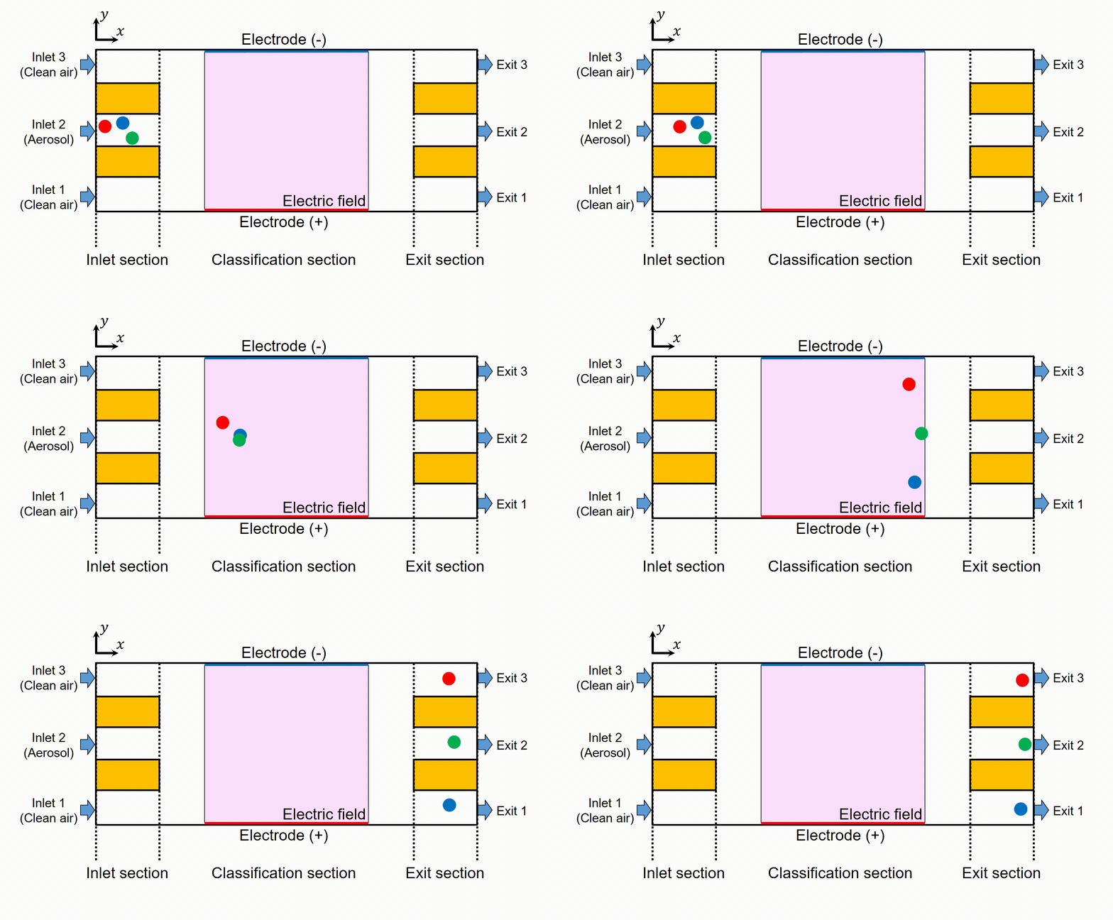
Particulate matter such as PM2.5 in inhaled air has adverse effects on human health by depositing on respiratory organs. Since charged particles deposit on the respiratory tracts more than non-charged particles, measurement of charging states of PM2.5 and charge distribution of ambient aerosol have been carried out. For measurement of charge of individual particle, the parallel plate particle separator (PPPS), shown in Fig. 1, is developed. Particles enter the PPPS from the central path of the inlet section. The other paths of the inlet section are for clean air. When particles flow in the classification section, they are moved toward the electrodes by Coulomb force. Since the drifting motion toward the electrodes depends on the charge number, particles are classified by their charging states at the exit section consisted of three paths. However, a problem that some particles flow out to unexpected paths has been observed in the experiment.
In the present study, we reveal its mechanism by means of numerical simulation, and conduct a parametric study for finding a condition that achieves a more accurate measurement. Lagrangian particle tracking method is used for computing the dispersion of particles in the PPPS. The particles are assumed as the PSL standard particles with a diameter of 0.37 μm and density of 1.04 g/cm3.
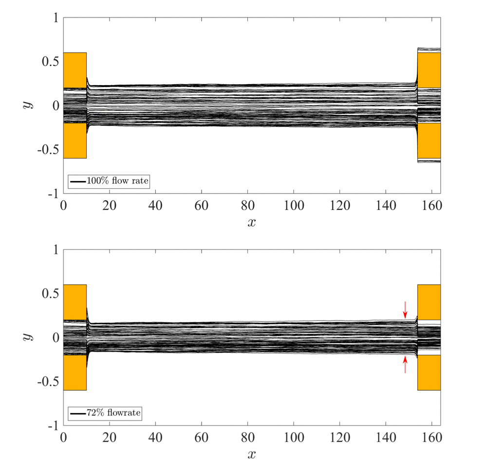
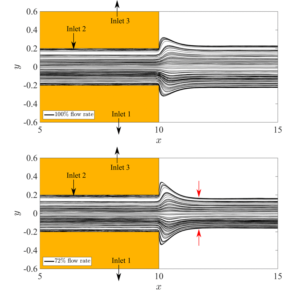
Figures 3 and 4 show the trajectories of 100 particles in the case of 100% aerosol flow rate and the case of 72% aerosol flow rate. In these cases, voltage is not applied to the electrodes in order to consider only the effect of flow field on particle trajectories. For the case of 100% flow rate, particles flow out to not only the central exit but also the left and right exits. For the case of 72% flow rate, the trajectories shift toward the center line of the PPPS. As a result, all particles flow out to the central exit. This is because flow toward the center of the PPPS is induced at the entrance of the classification section. This improvement is also confirmed by experimental observation. In addition, it is found that narrowing the width of the central inlet path decreases the number of particles flowing to Exit 1 and 3. Further, present results indicate that the distribution of particles in the inlet section is asymmetric in the experiments. This asymmetric initial distribution makes distribution of particles at the end of the PPPS asymmetric distribution and impacts accuracy of measurement. Development of a new device is ongoing based on the present results and detailed analysis with electric fields.
Key words
Aerosol, Classification, Particulate matter, Electrical mobility, Lagrangian particle tracking, Device optimization
Figures

Fig. 1 Schematic of the parallel plate particle separator and classification of aerosol particles.

Fig. 2 Trajectories of 100 particles in the case of 100% flow rate and 72% flow rate.

Fig. 3 Trajectories of 100 particles in the case of 100% flow rate and 72% flow rate around the inlet section.

