

Newsletter 2023.3 Index
Theme : "The Conference of Fluid Engineering Division (March issue)"
|
Breakage mechanism of a glass tube and development of crack-free system with generation of laser-induced microjets
 |
 |
 |
||
| Shoto SEKIGUCHI Tokyo University of Agriculture and Technology |
Kazuya U. KOBAYASHI Nippon Institute of Technology |
Yoshiyuki TAGAWA Tokyo University of Agriculture and Technology |
Abstract
Conventional needle-free injection devices are reported to cause severe pain because the liquid jet tip is larger than the nozzle diameter(1). The focused jet tip (Fig. 1) enables penetration into the skin without diffusing the liquid. Therefore, it is suggested that high stress can be suppressed and pain at the time of penetration can be reduced(2). Research on focused jet has so far mainly studied injection control, such as modeling of jet velocity and injection volume(3). However, for practical use, it is also important to establish an injection technology that guarantees safety. Therefore, I focused on the breakage of glass tube, which may occur accidentally during the jet generation process, and aimed to develop a crack-free system that can suppress the breakage of glass tube. First, the breakage mechanism was elucidated in order to develop an effective crack-free system. Secondly, various crack-free methods were evaluated and investigated. Finally, jet velocity and injection stability were investigated using jet injection systems developed by the author that enables breakage suppression.
The experimental setup is shown in Fig. 2 (left). An objective lens focuses a pulsed laser onto a liquid in a tube. The absorbed energy of the laser E is measured by an energy meter. An ultra high-speed camera with a frame rete of 5,000,000 fps is used to target ultra high-speed phenomena. Two types of liquids with different absorbance (magenta ink and pure water) are used in the tubes.
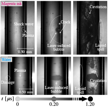
First, the breakage mechanism was elucidated in order to develop an effective crack-free system. In the experiment shown in Fig. 2(a), we observed the breakage phenomenon and visualized the shock wave using the shadowgraph technique. As shown in Fig. 3(a-1) and (a-2), cracks appeared when the shock wave reached the tube wall, especially in magenta ink. This phenomenon was similar for pure water, both of which showed characteristic breakage behavior symmetrical to the laser's focus axis. In order to clarify the specific breakage mechanism, the experiments shown in Fig. 2(b) were conducted to compare the behavior of crack growth as absorbed energy of the laser E. From the results shown in Fig. 3(b), it was considered that when the shock wave acts on the micro-defects potentially existing inside the glass, stress concentration is caused, resulting in breakage.
Next, we proposed several methods to suppress breakage caused by shock wave, as shown in the right side of Fig. 2, and evaluated and verified them. The most interesting crack-free method is a method that changes the numerical aperture (NA) of the objective lens and the results of the suppression are described. Fig. 4 shows that breakage was successfully suppressed when an objective lens with NA = 0.40 was applied. The larger the numerical aperture (NA), the shorter the plasma is in the center of the tube, which attenuates the wavefront pressure along the propagation distance to the tube wall, reducing the shock wave pressure and thus enabling breakage suppression(4).
Finally, based on the above evaluation and verification of the breakage suppression method, we investigated the injection performance when various jet generation conditions were combined, as shown in Table 1. Specifically, we investigated the average jet velocity and the standard deviation of jet velocityuntil inner wall damage occurs due to shock waves. In repeated use of the injection system, Fig. 5 shows that the use of glass tube with excellent transparency succeeded in generating a high-speed jet. Furthermore, the use of an objective lens with a large numerical aperture (NA) succeeded in generating a jet with stable jet velocity.
Key words
Needle-free injection, Laser-induced microjet, Breakage of glass tube, Shock wave
Figures
Figure 1 Video of laser-induced microjet (Frame rate : 5,000,000 fps, Shooting time : 10 µs, Jet velocity : 184 m/s).
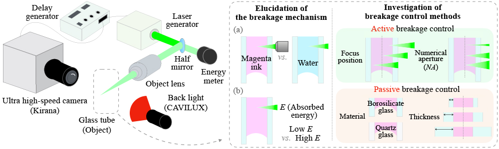
Figure 2 Experimental overview diagram. Left: A sketch of the experimental setup. Right: Details of experimental methods.
| (a-1) | |
| (a-2) | (b) |
 |
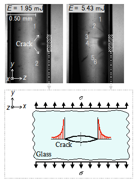 |
Figure 3 Ultra-high speed images of glass tube breakage phenomena. (a-1) Videos and (a-2) Time evolution of breakage phenomena (Visualization of shock waves using the shadowgraph technique.). (b) Crack growth with laser energy magnitude.
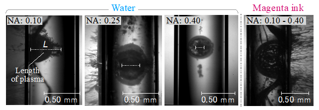
Figure 4 Generation positions of plasma and laser-induced bubble in the case of different objective lenses (NA).
Table 1 Experimental conditions.
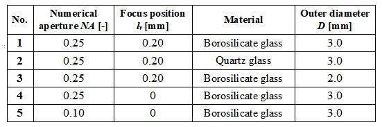
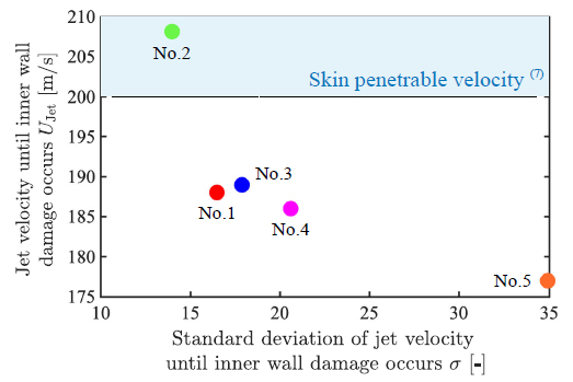
Figure 5 Average jet velocity![]() and standard deviation of jet velocity
and standard deviation of jet velocity![]() until inner wall damage occurs, depending on experimental conditions.
until inner wall damage occurs, depending on experimental conditions.