

Newsletter 2023.3 Index
Theme : "The Conference of Fluid Engineering Division (March issue)"
|
Gas removal from a closed-end hole by irradiating acoustic wave
 |
Yuta MATSUMOTO,
|
Abstract
Some product manufacturing processes, e.g., cleaning and painting, use liquids. Filling closed-end holes with liquid is necessary for these processes where the object is uneven. Usually, vapor or vacuum is used for liquid filling. To make it easier, we have developed a liquid infiltration method using acoustic wave irradiation for closed-end holes. In this method, the acoustic pressure oscillates the gas column in the hole and removes it. The liquid filling process, i.e., the gas removal, is divided into two stages: in the first stage, about 50% of the gas is removed as the air column oscillates and breaks up, and in the second stage, the divided bubbles are gradually removed. However, the entire removal mechanism needs to be clarified. This study focuses on the second stage.
We observed the gas removal of the multiple gas columns in the hole by irradiating acoustic waves with the experimental apparatus shown in Fig. 1. As shown in Fig. 2, the gas column in the back hole moves to the gas column near the inlet and the entire gas is removed as they repeatedly coalesce and break-up. Initially, a liquid film formation between the gas column and the wall due to the oscillation starts the gas column moving. Finally, gas removal occurred, as shown in Fig. 3. Focusing on the final gas removal in more detail, first, asymmetric gas column oscillation causes the propagation of capillary waves on the sides of the gas column (Fig. 3(i)). Necking occurs when the capillary waves attenuate (Fig. 3(ii)). The liquid film of the necking part merges, and the air column breaks into two columns. At the moment, two jets occur due to the air column's break-up, and the other capillary waves caused by the jet generation propagate the sides of the column. The capillary waves superimpose with gas bubble oscillation outside the hole, causing the bubbles to break up (Fig. 3(iii)). The break-up gas columns then move and coalesce again (Fig. 3(iv)). The repetition of the above process is our removal scenario from the high-speed observation.
Key words
Closed-end hole, Gas removal, Acoustic wave, Gas-liquid interface oscillation
Figures
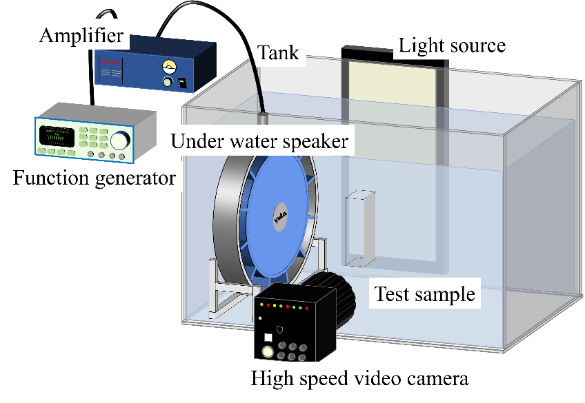
Figure 1 Schematic of experimental apparatus.
Figure 2 Experimental result of gas removal (playback speed ×0.2).
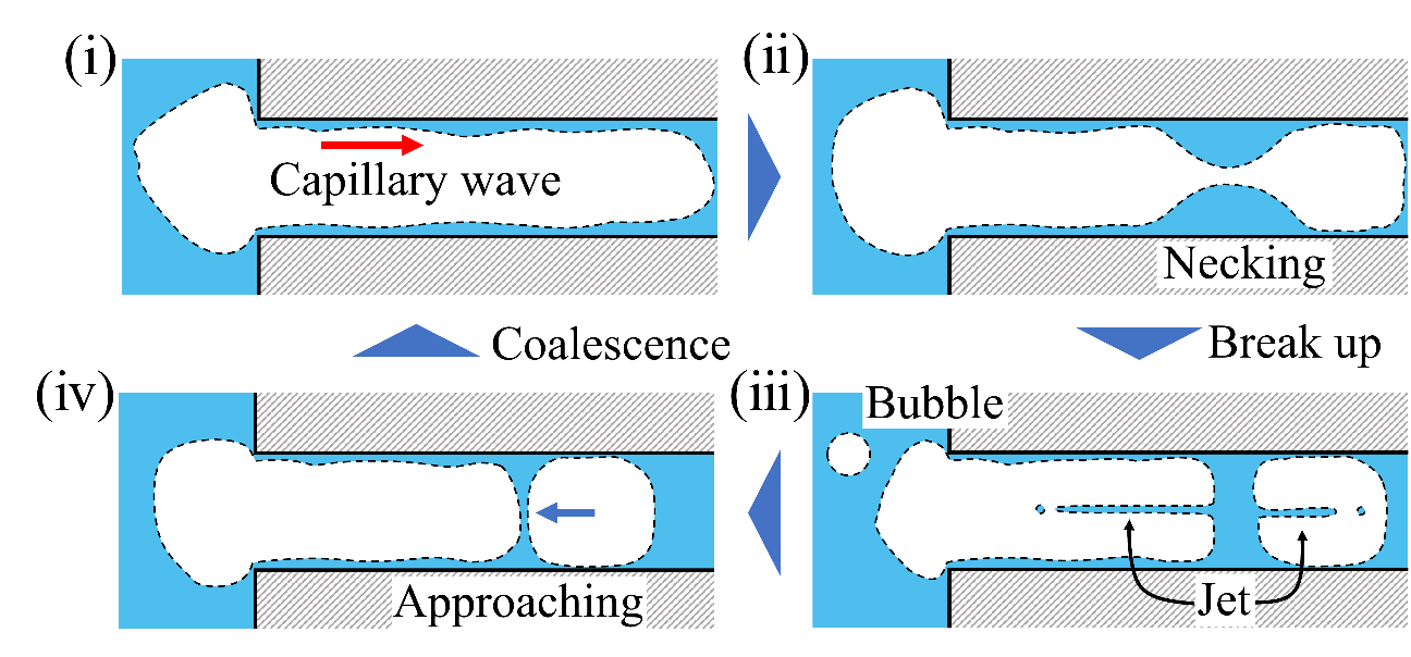
Figure 3 Schematic illustration of the final gas removal process, (i) Capillary wave propagation, (ii) Necking, (iii) break-up with jetting, and (iv) bubble coalescence.