

Unsteady behavior and mechanism of a rotating stall in a centrifugal compressor with vaneless diffuser
 |
 |
 |
 |
| Nobumichi FUJISAWA Waseda University |
Hiroshi MIIDA Honda R&D Co., Ltd. |
Kenta TAJIMA Komatsu Ltd. |
Yutaka OHTA Waseda University |
Abstract
Unsteady diffuser stall behavior in a centrifugal compressor with a vaneless diffuser was investigated by experimental and computational analyses. The test rig at Waseda University was used for a shipboard turbocharger, comprising of an impeller, vaneless diffuser, and volute. The impeller is an open-type with the tip clearance of 1.0% of the impeller blade width 105.6 mm. In the experiment, the impeller rotational speed was set to 6000 r/min. The diffuser stall generated as the mass flow rate decreased. The diffuser stall cell rotated at 25-30 % of the impeller rotational speed, with diffuser stall fluctuations observed at 180° from the cutoff. The diffuser stall fluctuation magnitude gradually increased near the cutoff. Based on diffuser inlet velocity measurements, the diffuser stall fluctuations generated near both the shroud and hub sides, and the diffuser stall appeared at 180° and 240° from the cutoff. According to the CFD analysis, the mass flow fluctuations at the diffuser exit showed a low mass flow region, rotating at approximately 25% of the impeller rotational speed. They began at 180° from the cutoff and developed as this region approached the cutoff. Therefore, the diffuser stall could be simulated by CFD analysis. First, the diffuser stall cell originated at 180° from the cutoff by interaction with boundary separation and impeller discharge vortex. Then, the diffuser stall cell further developed by boundary separation accumulation and the induced low velocity area, located at the stall cell center. The low velocity region formed a blockage across the diffuser passage span. The diffuser stall cell expanded in the impeller rotational direction due to boundary separation caused by a positive flow angle. Finally, the diffuser stall cell vanished when it passed the cutoff, because mass flow recovery occurred.
Keywords
Centrifugal compressor, Vaneless diffuser, Rotating stall, CFD, DES
Figures
Fig.1 Distributions of radial velocity fluctuation within the diffuser passage obtained by CFD analysis. The reverse flow region is the diffuser stall cell that induced the largest mass flow fluctuations. The region with the large velocity fluctuations was first generated at around 45°. Then, the large fluctuations region was formed at the diffuser exit area. After that, the diffuser stall cell expanded both radially and circumferentially as it approached the cutoff. Finally, the stall cell size reduced after passing the cutoff.
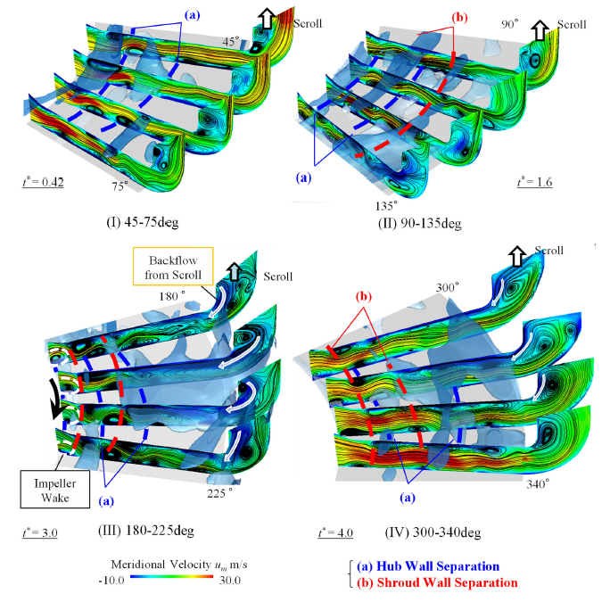
Fig.2 Meridional velocity distribution around the stall cell and the iso-surface of -10 m/s. The blue dashed line represents the hub wall separation and the red one indicated the shroud wall separation. The hub wall boundary layer separation initiated at around 45°. Then, this hub wall separation induced the next shroud wall separation because of a spanwise pressure gradient. The low velocity region within vaneless diffuser developed due to the boundary layer separations occurring on the shroud and hub wall by turns. Finally, the low velocity region formed the entire diffuser passage span blockage. After passing cutoff, the size of boundary layer separations occurring on the shroud and hub wall was decreased and the reverse flow from the casing was diminished.
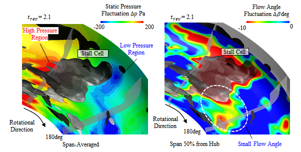
Fig.3 Distributions of span averaged pressure fluctuations and flow angle fluctuations around the stall cell. The static pressure was increased behind of the stall cell as the main flow collided with the low velocity area. The static pressure was decreased ahead of the rotating stall because of merging the impeller discharge flow and the reverse flow from the casing. In addition, the flow angle was decreased by merging the impeller discharge flow and the reverse flow from the casing.
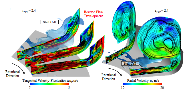
Fig.4 Distributions of tangential velocity fluctuations and radial velocity within diffuser and casing passages around the stall cell. The reverse flow was developed by the evolution of separation vortex at diffuser exit because of the low-pressure area ahead of the stall cell. The boundary layer separations started occurring on the shroud and hub wall ahead of the stall cell due to the small flow angle.
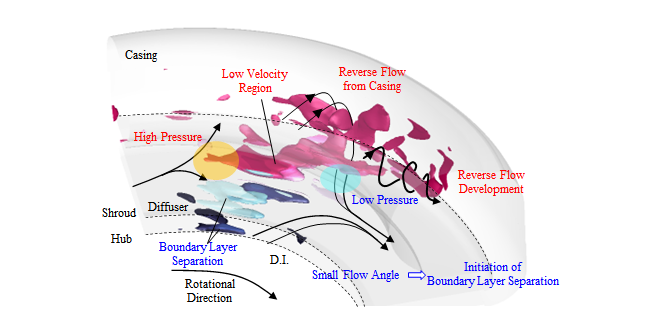
Fig.5 Sketch and rotating mechanism of diffuser stall cell. The static pressure was decreased ahead of the rotating stall because of merging the impeller discharge flow and the reverse flow from the casing. In addition, the flow angle was decreased by merging the impeller discharge flow and the reverse flow from the casing. Therefore, the boundary layer separations started occurring on the shroud and hub wall ahead of the stall cell. The rotating mechanism of diffuser stall was induced by the reverse flow development and decrease of flow angle ahead of the stall cell.