

遠心圧縮機の羽根なしディフューザで発生する旋回失速の非定常挙動と構造
 |
 |
 |
 |
| 藤澤 信道 早稲田大学 |
三井田 弘 本田技術研究所 |
田島 健太 小松製作所 |
太田 有 早稲田大学 |
1. 緒言
ターボ機械のひとつである遠心圧縮機は,部分流量運転時にサージや旋回失速といった非定常現象が発生することで効率の低下だけでなく,機器や配管系の破損を招く危険性があることが知られている.サージの予兆現象として発生する旋回失速については,その発生機構や非定常的な渦構造の解明が進められているが,渦型室の非軸対称性や羽根車流路間の流体に働く慣性力により内部流れ場が複雑となっているため,失速の非定常的な流動構造を詳細に解明した研究報告は少ないのが現状である.
幅広い流量域において運転される遠心圧縮機においては,羽根なしディフューザが多用されているため,羽根なしディフューザで発生する旋回失速の研究報告がいくつかなされている.初期の研究としては,旋回失速の初生と逆流との関連を調査したSenooらによる報告が挙げられ,旋回失速の初生基準(臨界流れ角)が提唱されている(1)(2).辻本らは簡易な二次元線形解析を用いて,ディフューザ旋回失速の発生条件やその伝ぱ速度を求めている(3).また近年では,試験による詳細な計測結果に数値解析結果を援用して,ディフューザ失速発生時の境界層剥離の様相と伝ぱ機構が検討されていたり(4),ディフューザ失速からサージに陥る過程が調査されている(5).一方,数値解析を用いた報告例としては,サージ点近傍における非定常DES解析の結果から,ディフューザ内部流れを明らかにした例(6)や,ディフューザ失速初生からサージに陥るまでの過程を詳細に明らかにした例(7)がある.しかし,羽根なしディフューザで発生する旋回失速の非定常挙動やその旋回機構を,境界層剥離と渦型室の形状に起因する非軸対称な流れ場と関連付けて,明らかにした例は少ない.
そこで本研究では,羽根付ディフューザで発生する旋回失速の調査で開発した数値解析コードや得られた知見(8)(9)を用いて,羽根なしディフューザを有する遠心圧縮機における旋回失速の非定常的な渦構造およびその旋回機構を解明することを目的とし,試験および数値解析を実施した.
2.実験および数値解析手法
供試圧縮機は舶用ディーゼルエンジンに用いられる過給機用遠心圧縮機を過渡現象試験用に改造したもので,羽根車にはインデューサを有する長羽根7枚,短羽根7枚から構成される開放型羽根車,ディフューザには羽根なしディフューザを採用している.実験条件である回転数6000 min-1における質量流量および圧力比はそれぞれ1.64kg/s,1.1である. 圧縮機内部に発生する非定常現象を調査するために,ディフューザ流路中央において周方向に圧力変動計測,およびディフューザ流路内での周方向・子午面方向に流速の非定常計測を実施した.また,ディフューザ側壁上の流れを油膜法により可視化した.
一方,圧縮機内部の詳細な流れ構造の把握にはDES解析(10)を実施した.計算領域は,相対系で取り扱う羽根車領域,絶対系で取り扱うディフューザ領域,そして渦型室領域の3領域である.格子点数は翼端隙間を含んだ羽根車領域では約3200万点,ディフューザ領域は約1100万点,渦型室領域は約2200万点であり,総格子点数は約6500万点である.境界条件として,入口境界には大気圧からの等エントロピおよび等エンタルピを仮定し,大気圧,標準温度を全圧・全温度として固定した.出口境界には,質量流量固定条件を付与した.
実験装置と数値解析法の詳細については,関連報告(8)(9)を参照されたい.
3.ディフューザ失速の非定常挙動
ディフューザ内部の半径方向流速変動を可視化した結果を図1に示す.半径方向流速変動が負となる領域が失速セルに対応するが,羽根車1周に要する時間を基底とした無次元時間trev = 0.94において45度付近から初生し,trev = 1.16以降の失速セルが90度を過ぎた後は,ディフューザ出口側からの逆流が増大することで,半径方向および周方向に拡大しながら舌部に向って旋回していく.その後trev = 3.60以降の失速セルが舌部を通過した以降は,変動の大きさが低下し,失速セルは消滅へと向う.
Fig.1 Distributions of radial velocity fluctuation within the diffuser passage obtained by CFD analysis. The reverse flow region is the diffuser stall cell that induced the largest mass flow fluctuations. The region with the large velocity fluctuations was first generated at around 45°. Then, the large fluctuations region was formed at the diffuser exit area. After that, the diffuser stall cell expanded both radially and circumferentially as it approached the cutoff. Finally, the stall cell size reduced after passing the cutoff.
ディフューザ流路から渦型室入口部までの子午面流速分布を図2に示す.図中には,子午面流速分布と共に半径方向流速-10 m/sの等値面を付記している.また,(a)の青破線がHub壁面境界層の剥離線に,(b)の赤破線がShroud壁面境界層の剥離線の位置に対応している.図より,ディフューザ失速セルはHub壁面の境界層剥離が集積することで初生し,ディフューザのHub,Shroud壁面交互の境界層剥離および渦型室からの逆流を伴いながら拡大・旋回すると考えられる.旋回失速セルの構造および規模は周方向位置によって異なる様相を呈しており,同様に子午面方向にも複雑な特性を持つことがわかる.
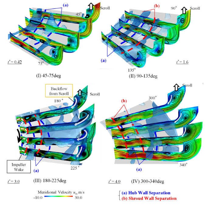
Fig.2 Meridional velocity distribution around the stall cell and the iso-surface of -10 m/s. The blue dashed line represents the hub wall separation and the red one indicated the shroud wall separation. The hub wall boundary layer separation initiated at around 45°. Then, this hub wall separation induced the next shroud wall separation because of a spanwise pressure gradient. The low velocity region within vaneless diffuser developed due to the boundary layer separations occurring on the shroud and hub wall by turns. Finally, the low velocity region formed the entire diffuser passage span blockage. After passing cutoff, the size of boundary layer separations occurring on the shroud and hub wall was decreased and the reverse flow from the casing was diminished.
4.ディフューザ失速の旋回機構
図3に180度位置に存在する失速セル周りのスパン方向に平均化を施した静圧変動分布と,流れ角変動分布を示す.図中には半径方向流速-10 m/sの等値面を付記している.失速セルの前縁側では低圧領域,後縁側では高圧領域が形成されることが確認された.高圧領域は失速セルを構成する低速領域に主流が衝突することにより生じ,一方の低圧領域は失速セルを避けて失速セルの前縁側へと流れた羽根車吐出流と渦型室からの逆流が合流することによる周方向流速の加速の影響により生じることがわかる.このように,失速セル周りの流れにはディフューザ内部流れだけでなく,羽根車吐出流や渦型室からの逆流が強く影響を与えている.
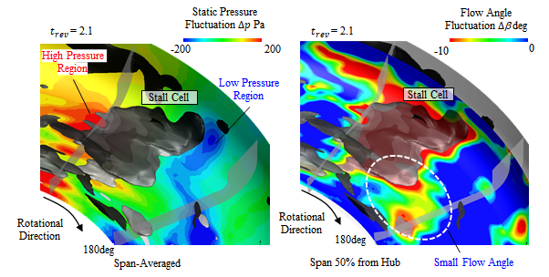
Fig.3 Distributions of span averaged pressure fluctuations and flow angle fluctuations around the stall cell. The static pressure was increased behind of the stall cell as the main flow collided with the low velocity area. The static pressure was decreased ahead of the rotating stall because of merging the impeller discharge flow and the reverse flow from the casing. In addition, the flow angle was decreased by merging the impeller discharge flow and the reverse flow from the casing.
失速セル周辺の圧力場や流れ角が失速の旋回機構に与える影響を調査するため,失速セル周辺の周方向流速変動分布を図4左図に,半径方向流速分布を図4右図に示す.ディフューザ流路間では失速セルの前縁側からHub, Shroud壁面交互の境界層剥離が初生し始め,失速セルに近づくにつれその規模が大きくなっている.これは,図3に示したように失速セルの前縁側では流れ角が小さくなるために,壁面での剥離が誘起されやすくなったためである.また,ディフューザ出口部Shroud側での剥離渦も失速セルに近づくにつれ大きくなり,セルの中心では大きな逆流領域へと成長している.これは,図3に示した低圧領域に渦型室の流れが引き寄せされているためである.さらに,低圧領域が存在する失速セルの前縁側では,後縁側と比較して渦型室入口曲がり部での剥離渦の規模が大きくなっていることがわかる.
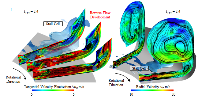
Fig.4 Distributions of tangential velocity fluctuations and radial velocity within diffuser and casing passages around the stall cell. The reverse flow was developed by the evolution of separation vortex at diffuser exit because of the low-pressure area ahead of the stall cell. The boundary layer separations started occurring on the shroud and hub wall ahead of the stall cell due to the small flow angle.
以上の結果を踏まえて,失速セルの内部構造と旋回機構を図5にまとめた.ディフューザ流路間および渦型室内部の低速領域の等値面を可視化しており,境界層剥離に起因するものを青色,渦型室からの逆流に起因するものを赤色で示している.ディフューザ失速セルはHub,Shroud壁面交互の境界層剥離と渦型室からの逆流に起因するディフューザ出口部の低速領域で構成される.また,失速セル周辺では,失速セルの後縁側にて低速領域に主流が衝突することにより生じる高圧領域,失速セルの前縁側での周方向流速の加速の影響による低圧領域が形成される.低圧領域に渦型室の流れが引き寄せされるために,渦型室入口では逆流領域が失速セルに近づくにつれ成長する.また,羽根車吐出流と渦型室からの逆流が合流することにより,流れ角が小さくなることで,失速セルの前縁側ではHub, Shroud壁面交互の境界層剥離が初生する.つまり,失速セルはHub, Shroud壁面交互の境界層剥離と渦型室からの逆流が周方向に初生・成長していくことで,低速領域を形成しながら旋回していくと考えられる.
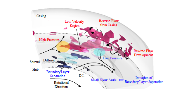
Fig.5 Sketch and rotating mechanism of diffuser stall cell. The static pressure was decreased ahead of the rotating stall because of merging the impeller discharge flow and the reverse flow from the casing. In addition, the flow angle was decreased by merging the impeller discharge flow and the reverse flow from the casing. Therefore, the boundary layer separations started occurring on the shroud and hub wall ahead of the stall cell. The rotating mechanism of diffuser stall was induced by the reverse flow development and decrease of flow angle ahead of the stall cell.
5.まとめ
羽根なしディフューザを有する遠心圧縮機に発生する失速現象の非定常挙動および構造を調査するために実験および数値解析を行い,ディフューザ失速セルの初生,成長・拡大および消滅に至る過程を把握し,周方向の逆圧力勾配によって生じるHub壁面境界層の剥離や渦型室からの逆流が顕著な影響を与えていることを示した.また,失速セルの構造を詳細に調査することで,Hub, Shroud壁面交互の境界層剥離と渦型室からの逆流が周方向に初生・成長していくことが失速セルの旋回機構であることを示した.