

Newsletter 2022.3 Index
Theme :"The Conference of Fluid Engineering Division (March issue)"
|
Investigation of friction torque loss in a narrow gap between a rotating and a stationary disk in a centrifugal impeller
|

Abstract
It has been frequently reported that disk friction loss is a major concern in design of low specific-speed centrifugal pumps. To understand the mechanisms of loss generation in low specific-speed centrifugal pumps, the friction loss acting on a rotating disk is investigated by experiments and numerical methods.
Figure 1 shows the current experimental apparatus simulating the clearance flow between rotating impeller and stationary casing as such in centrifugal pumps. Moreover, CFD analyses are carried out to compare with experimental results. For numerical computations, one periodic boundary area of the full domain is selected (as shown in figure 2) to study the effects of the Reynolds number and the clearance ratio S/D for disk friction loss where S is a width of the clearance and D is a diameter of rotating disk. Disk friction coefficient Cm = 2Mρ/R5ω3 is used for evaluation of disk friction loss where M is a measured torque of the disk.
According to Kurokawa’s theoretical formula [1], Cm can be predicted by using rotational Reynolds number of the disk Cm = Re-1/5, therefore several cases of Reynolds number are studied by changing both the disk peripheral speed and the viscosity of water depending on its temperature to consider the influence on each of these parameters.
The results of our experiments and CFD analyses indicate a similar tendency with Kurokawa’s prediction Cm = Re-1/5(as shown in figure 3). The relation between Cm and Re that previous experimental studies showed is also well predicted by the CFD results, therefore our results are qualitatively in good agreement with experimental ones under turbulent condition. The reason the CFD results are not quantitatively consistent with experimental results is that the CFD ones consider the friction loss acting on only a lower surface of the rotating disk.
Figure 4 shows the internal flow of the CFD results for several cases of Reynolds number by changing both the disk peripheral speed and the viscosity of water. The results show that peripheral speed of the disk affects the velocity gradient in the radial direction as a vortex is formed in the clearance. The viscosity of water also affects the vortex size, in addition to the friction torque acting on the rotational disk surface.
Figure 5 shows effects of the clearance ratio (S/D) on disk friction coefficient obtained by CFD. From the results, it is confirmed that the boundary layers on both wall surfaces inside the clearance interfere when the clearance width is small. Reverse flow on the stationary wall increases as increasing the gap, it also causes larger friction torque.
Summarizing above, we found methods for reduction of the friction torque by choosing optimum value of disk clearance width which differs depending on the flow direction.
Key words
Disk friction, Clearances, Centrifugal Pumps, Computational fluid dynamics
References
| [1] | Kurokawa J., and Toyokura T., 1976, “Leakage loss and disk friction loss of centrifugal turbomachinery,” Turbomachinery, 4(5), pp. 302-310. |
Figures
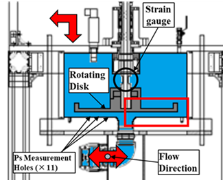
Figure 1 Experimental Equipment
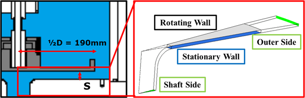
Figure 2 Analysis Domain
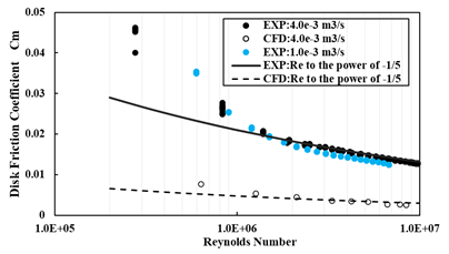
Figure 3 Pressure coefficient distribution in the radial direction (Outflow)
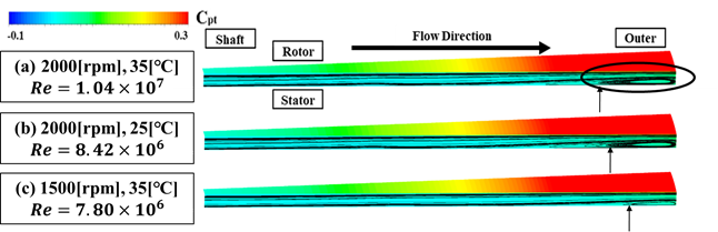
Figure 4 Total Pressure coefficient distribution and streamline (Outflow,Q = 4.00×10⁻³[m3/s] )
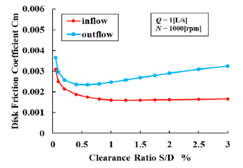
Figure 5 The influence of clearance ratio S/D on disk friction coefficient