

Newsletter 2019.3 Index
Theme : "Mechanical Engineering Congress, 2019 Japan (MECJ-19)”
|
A Case Study of Experimental Fluid Dynamics in a Company (Taking Cavitation Experiments as Examples)
Motohiko NOHMI EBARA Corporation
|

Abstract
It is mandatory for hydro machinery manufacturers to deal with cavitation problems. Major problems caused by cavitation include reduced performance of fluid machinery, vibration and noise, and erosion. In recent years, various numerical analyzes have progressed, and the aforementioned performance degradation can be relatively well predicted by CFD. Numerical prediction of vibration, noise, and erosion are under development. Experiments are indispensable for elucidating phenomena and building computation models. Experiments that evaluate performance degradation of pumps due to cavitation are called suction performance tests and are routinely performed as part of standard performance verification tests. On the other hand, specialized experiments are planned to achieve various research subjects. This paper introduces three cases of these special experiments. Finally, the author's personal opinion on experimental research in companies will also be written down.
Key words
Cavitation, Computational Fluid Dynamics, Hydrofoil, Pump, Erosion, Piezoelectricity
Figures
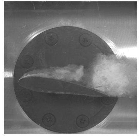
Figure 1 High speed photograph of cavitation on the hydrofoil of Clark Y 11.7%
(The flow is from left to right)
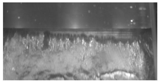
Figure 2 Complicated structure of the sheet cavity at the leading edge of the hydrofoil
(The flow is from top to bottom)
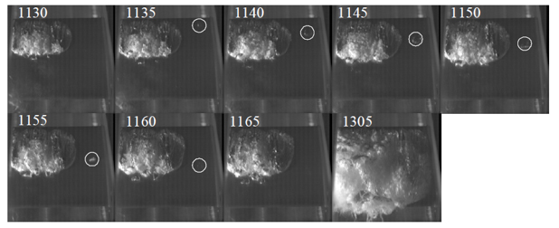
Figure 3 Single bubble running side by side with sheet cavitation (The flow is from top to bottom)
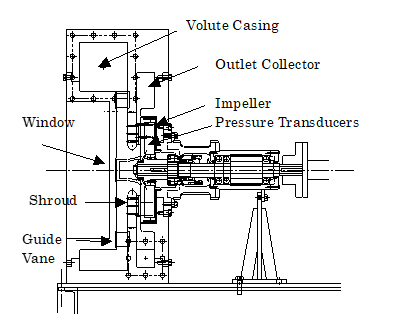
Figure 4 Cross sectional view of a test pump
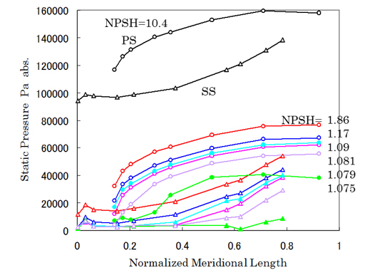
Figure 5 Static pressure distribution on the impeller blade at pump head breakdown in the best efficiency point flow (PS : Pressure Side, SS : Suction Side)
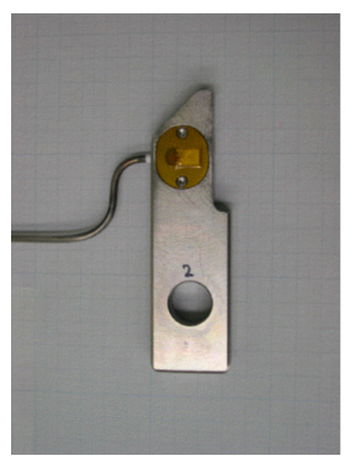
Figure 6 Piezoelectric force transducer of PVDF Film
(Yellow part is a polyimide film for protection of PVDF sensing element.)
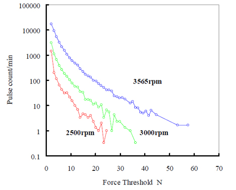
Figure 7 Pulse height spectra of cavitation impact force at the inducer rotation speed of 2500, 3000 and 3565rpm