

Newsletter 2025.3 Index
Theme : "The Conference of Fluid Engineering Division" (Part 2)"
|
Effects of Airfoil Surface Orientation on the Output Characteristics of a V-Type Vertical Axis Wind Turbine with NACA0018-Based Blades
 |
| Sho OOI, Moch Fakhrul FAUZI, Takanori BABASAKI, Ryo SAKURAI, Takaaki KONO, Takahiro KIWATA, Nobuyoshi KOMATSU Kanazawa University |
Abstract
We conducted wind tunnel experiments and computational fluid dynamics (CFD) analysis to investigate the effects of coning angle and airfoil surface orientation on the performance characteristics of a V-type vertical axis wind turbine (V-VAWT) equipped with NACA0018-based blades.
Fig.1 shows the designed model of V-VAWT with two blades. Two types of blade shapes, namely, normal blades and tilted blades, were utilized (Fig.2). The straight line connecting the 25% chord from the leading edge of the blade at each height is termed the “blade-root-rotational axis.” The angle between the blade-root-rotational axis and the horizontal plane is referred to as the “corning angle (β)”. For normal blades, the cross sections perpendicular to the blade-root-rotational axis have the NACA airfoil shape. For tilted blades, when β = 45°, the horizontal cross section of the blades has the same airfoil profile as the normal blade. The wind speed was 7 m/s. In the experiment, the torque of the wind turbine was measured. The flow field was assumed to be three-dimensional, unsteady, incompressible, viscous flow, with the Large Eddy Simulation (LES) method using the Wall-Adapting Local Eddy-viscosity (WALE) model for turbulence modeling. OpenFOAM 5.0 and OpenFOAM v2206 were used for CFD simulation.
Fig.3 shows the results of the CP - λ curves. The experimental results showed that the highest power coefficient was obtained with normal blades at a coning angle of 50° and a tip speed ratio of 3.2, while for tilted blades, the highest power coefficient occurred at the same coning angle but with a tip speed ratio of 3.7. The CFD analysis showed that the torque coefficient per blade was highest at the most upwind azimuth angle and at 70% of the blade length from the blade bottom edge for both blade configurations (Fig.4). However, near the most downwind azimuth angles, the torque in the small section near the blade tip was significantly higher for the normal blade than for the tilted blade (Fig.4). This could be attributed to the suppression of positive pressure near the leading edge of the blade, likely caused by the reduced upward flow along the blade surface.
Key words
Vertical axis wind turbine, Wind power, Wind tunnel, CFD
Figures
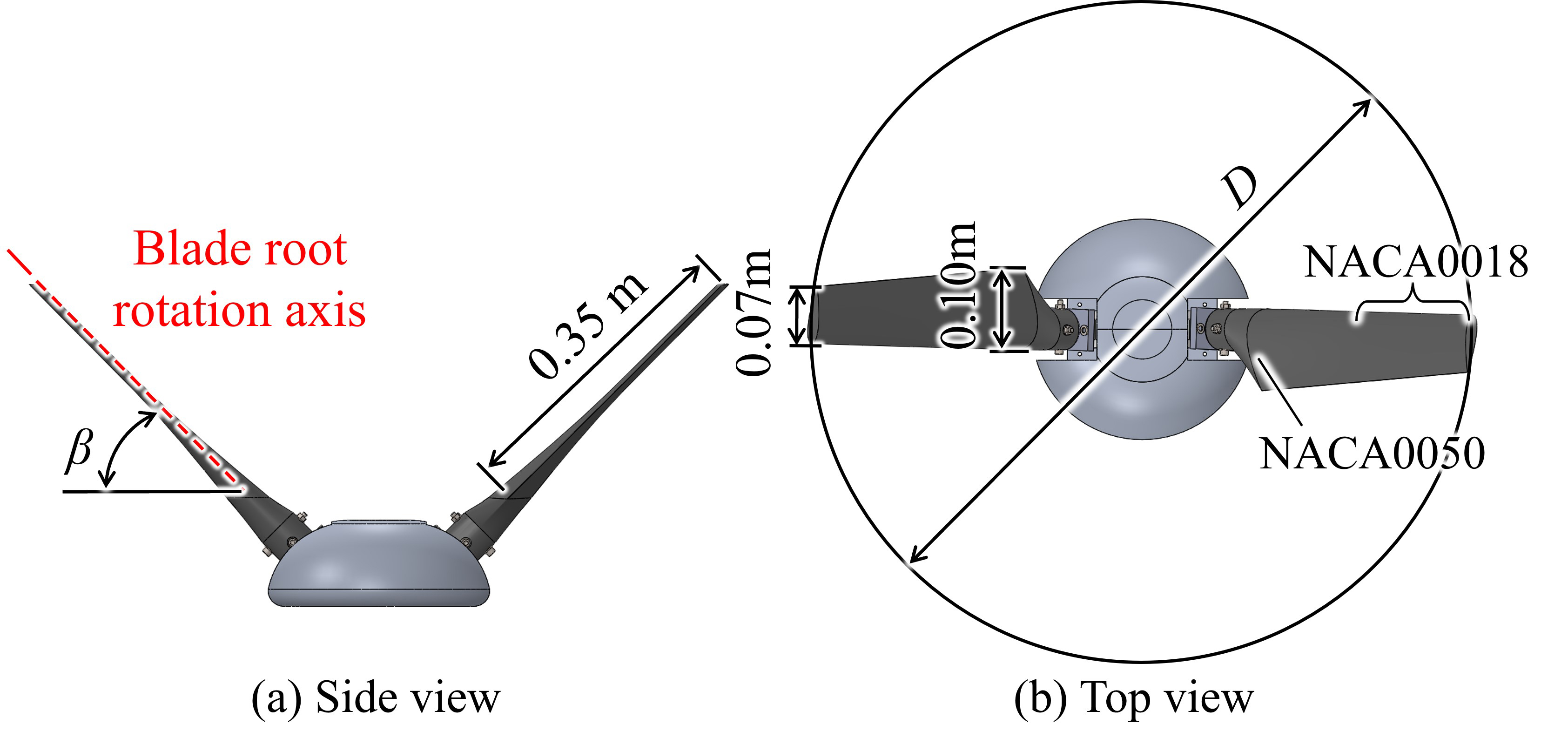
Fig. 1 Designed model of V-VAWT with 2 blades
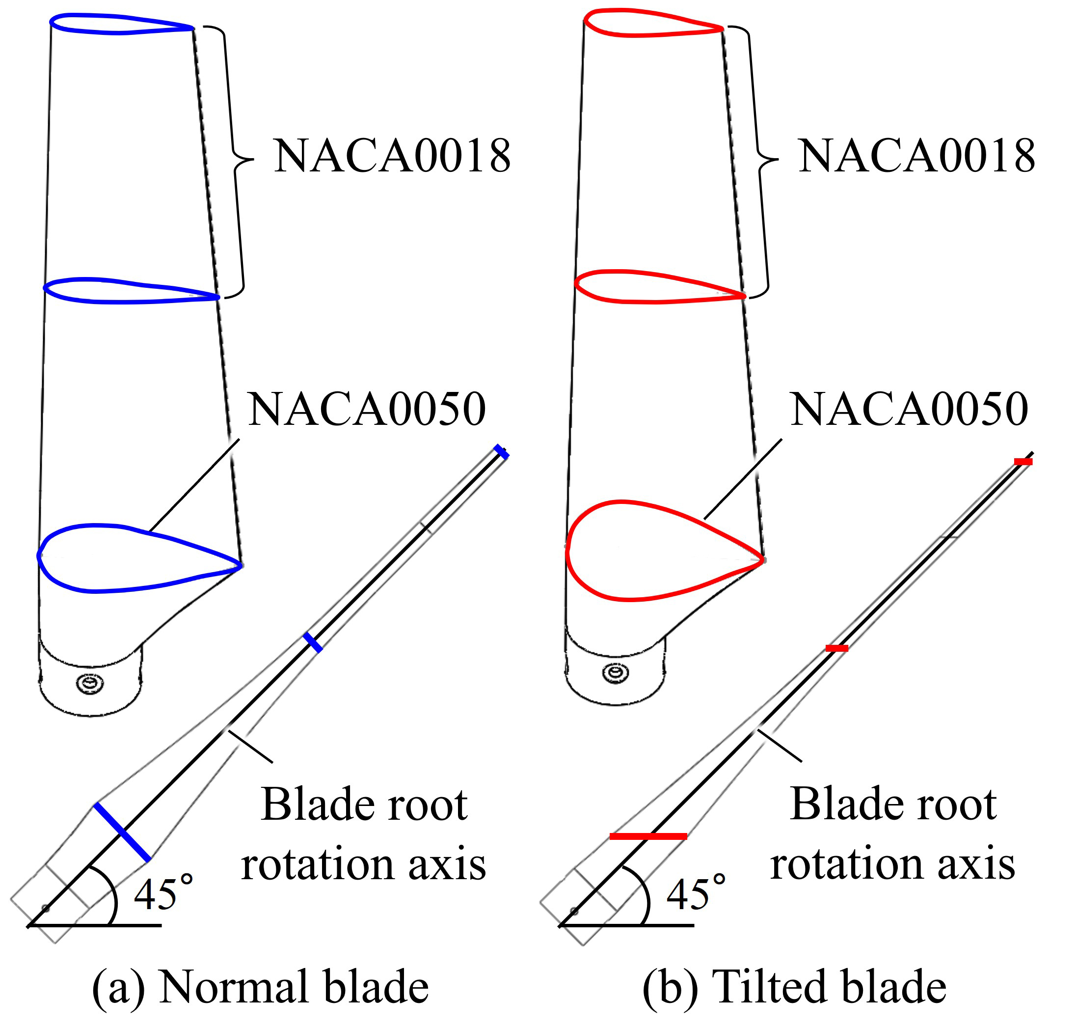
Fig. 2 Shape of blades
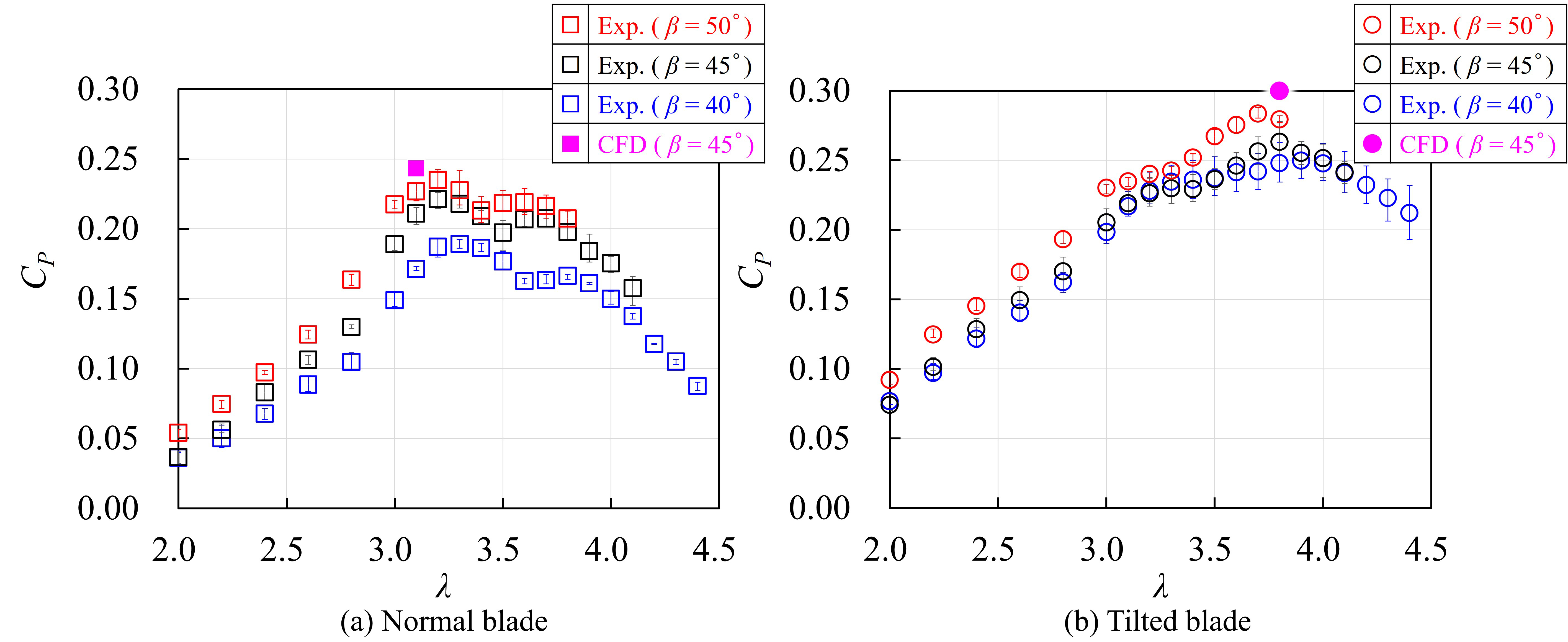
Fig. 3 CP –λ curve
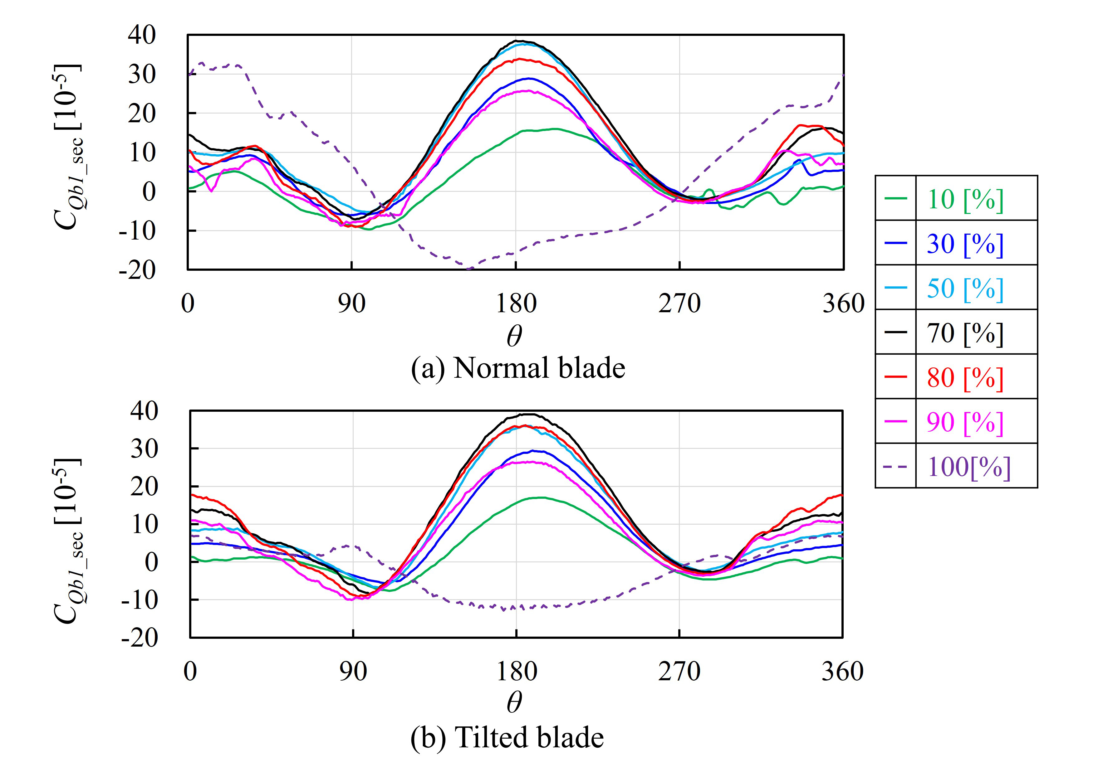
Fig. 4 Sectional torque coefficient of a blade vs. azimuth angle