

Newsletter 2026.3 Index
Theme : "The Eleventh JSME-KSME Thermal and Fluids Engineering Conference (TFEC11) "
|
Flow characteristics of multiple jets and their flow in a chamber
 |
 |
| Asuka KONDO Kyushu Institute of Technology |
Masaki FUCHIWAKI Kyushu Institute of Technology |
Abstract
Multiple jets are widely used in various manufacturing processes, including cleaning, drying, and surface treatment. Because the characteristics of multiple jets are related to mass transfer in chemical reactions, uniform nozzle flow velocities are required. However, in current equipment, nozzle flow velocities vary, with some nozzles having lower flow velocities than surrounding nozzles. Previous studies on nozzle jet characteristics have revealed that nozzle geometry and inlet conditions affect jet characteristics. However, the behavior of the liquid before it leaves the nozzle and its effect on the liquid flow at the outlet has not yet been clarified. To achieve uniform multiple jets, it is necessary to clarify the correlation between the liquid flow in the chamber and the jet characteristics and control these flows. Therefore, the purpose of this study is to clarify the flow characteristics in the chamber and elucidate the effect of these flows on the jet characteristics to achieve uniform jet characteristics. Specifically, by changing the inlet conditions of the multiple jets and performing transient analysis, we captured the liquid flow in the chamber and correlated it with the nozzle jet flow velocity. It is known that multiple parallel flows affect each other depending on the distance and flow velocity. Because it is not easy to change the internal structure of this model, the flow within the chamber was changed by changing the flow interference rather than the structure. Therefore, to clarify how the liquid flow within the chamber changes due to changes in the inlet flow rate ratio, the total inlet flow rate was kept constant (Q = 110 L/min) and two different inlet flow rate ratios were given. As a result, it was found that by providing flows with different flow rates to multiple inlets, it was possible to suppress the formation of large circulating flows within the chamber, and by equalizing the pressure distribution within the chamber, it was possible to obtain jets with uniform flow rates from all nozzles.
Key words
CFD, Jet, Pipe flow, Vortex flow
Figures
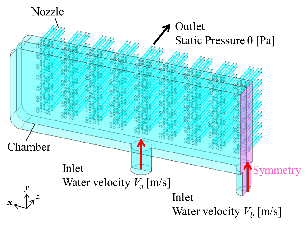
Fig. 1 Analysis model
(a) Evaluation cross section (c) Va:Vb = 1:2 (Q = 110 L/min)
Fig. 2 Pressure distribution in the nozzle and velocity vector at the nozzle outlet
(a) Va:Vb = 1:1 (Q = 110 L/min) (b) Va:Vb = 1:2 (Q = 110 L/min)
Fig. 3 Vorticity contour in the chamber